Updated case for the zBitx radio
A couple things have always annoyed me about the zBitx amateur radio. First, the exposed batteries with their barrel connector cord, that you just plug in / unplug. Seems so barbaric to me. Second, that it gets pretty warm, especially when using FT8. In and of themselves not huge issues but something that could be improved upon.
So I decided to challenge myself to come up with a solution. What follows is my solution.
Required parts:
- 1 set of 3D printed parts from Thingiverse
- 2 pairs of male/female connector cables
- 4x battery buckles
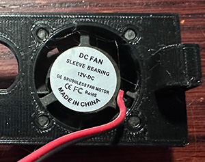
- 1x 25mm x 25mm 12V fan
- 1x Rocker Switch
- 10x 6mm x 2mm craft magnets
- 2x spade connectors to fit rocker switch
- 6x M3x12mm Button head screws
- 2x M3 hex nuts
- A few pieces of wiring
- (optional) Heat shrink tubes
Useful tools:
Assembly
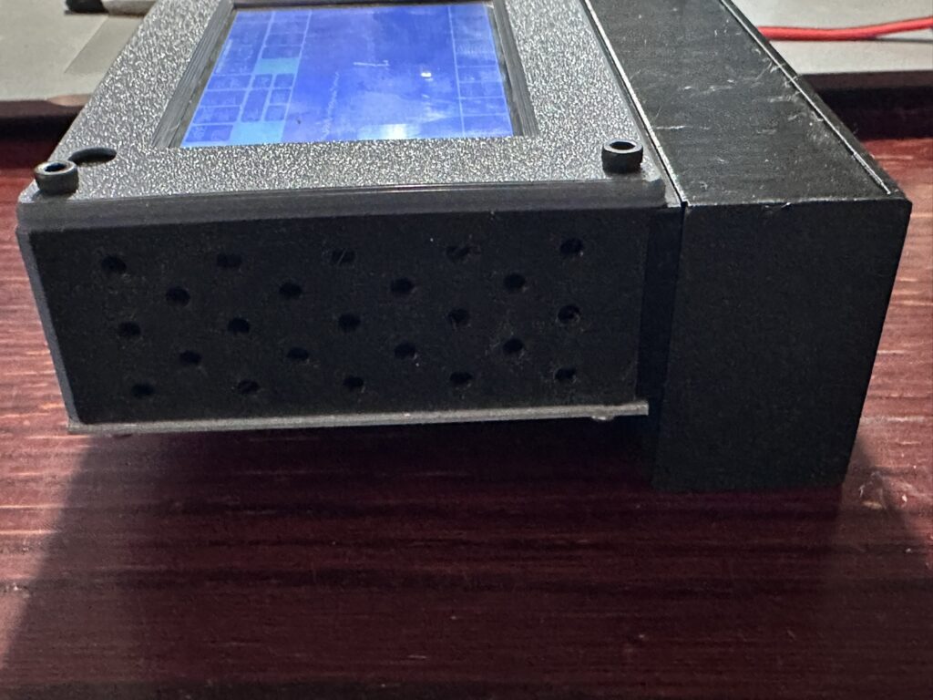
Start by printing all the parts from Thingiverse. I printed mine in PETG for a little better durability but you’re welcome to print them however you see fit. You should have a left side, right side and bottom that generally match up with the parts already on the zBitx; and a new battery holder, bottom extension and lid. Then glue the magnets into their holes in the lid and bottom extension. Make sure you orient the magnets correctly so the lid attracts to the extension instead of repelling it. I found it easiest to glue all the magnets into the bottom extension first, then put magnets for the lid on top of those and mark the side facing up with a sharpie. That way when I transferred them to the lid I made sure the mark was towards the lid and the polarity would be correct.
Next take two of the connector cables making sure they are the same gender. These will be soldered to the zBitx and connect to the fan and to the battery. Solder both black wires and both red wires together and add a short piece of wire to each to make it easier to solder onto the zBitx board. Make sure the solder is covered with either heat shrink or electrical tape because these will be loose inside the radio and we don’t want them shorting out on anything.
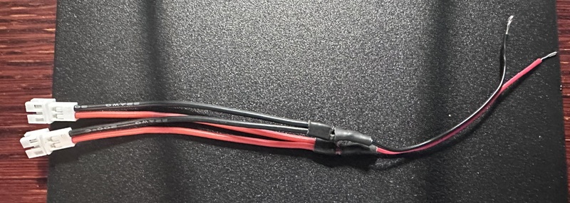
.
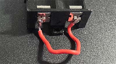
Then take 2 of the battery buckles and solder a short piece of wire between them. Clip them onto one end of the battery holder.
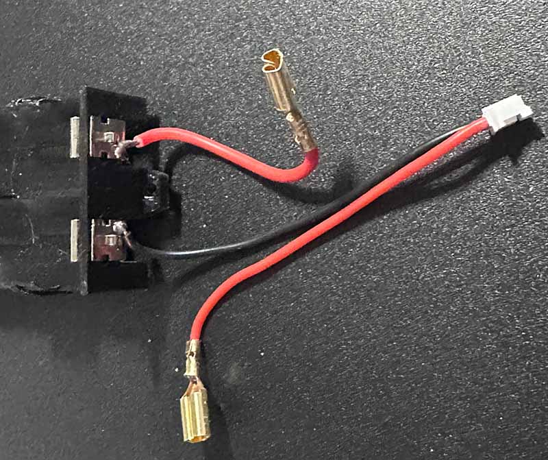
Next take the other 2 battery buckles, on one solder a short piece of wire with a spade connector on the other end. This will go from the positive battery terminal to the On/Off Switch. On the last battery buckle, solder the negative side of a connector cable. Make sure it’s the opposite gender of the connectors on the Wye you created above. Finally, solder another spade connector to the positive wire from the connector. Attach the battery buckles to the battery holder. You should end up with something like the below image:
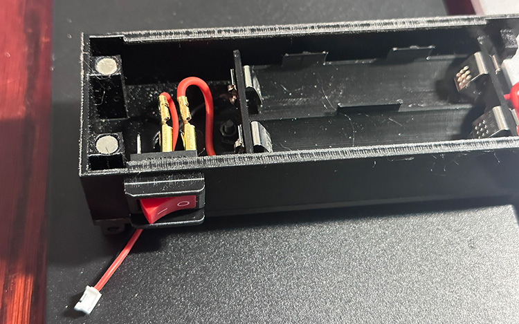
Now, assemble the bottom extension by stacking the bottom plate, extension and battery holder so all the holes line up and secure them with two M3 x 12mm screws and nuts. For the battery holder, make sure the end with the spade connectors is closest to the cutout for the on/off switch. Insert the on/off switch and attach the spade connectors to the proper terminals. Push the connector and remaining cable through the larger hole in the extension/plate. The bottom is now ready for the batteries and lid.
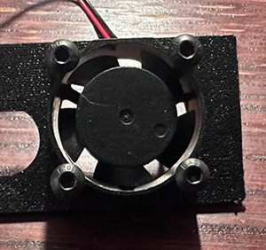
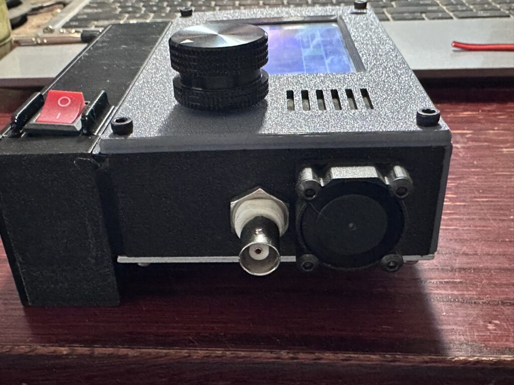
Take the fan and make sure the cable extends to the interior of the right side plate. Using 4 of the M3 x 12mm screws attach the fan to the plate. The 12mm screws should screw into the plate, but if you’d like a more secure solution use longer screws and nuts to secure the fan.
Next we come to the fun part. Or the scary part depending on how you look at it. We’re going to solder the loose ends of the wye connector to the main board. Disassemble your zBitx down to the main board. In the lower left corner find the Voltage Regulator marked U2. This is where we’re going to attach the leads to supply power to the regulator.
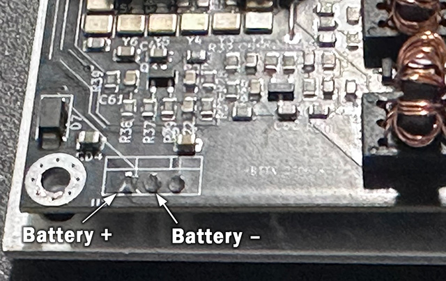
The positive lead from the battery will need to be soldered to the left-most pin protruding through the board. This is the input to the voltage regulator. The negative lead from the battery will be tied into the ground at the middle pin of the regulator. Once the wires are soldered, route the wires so one connector exits the bottom and the other exits on the right. Try to make sure both cables extend beyond the sides of the board to facilitate connecting them once assembled.
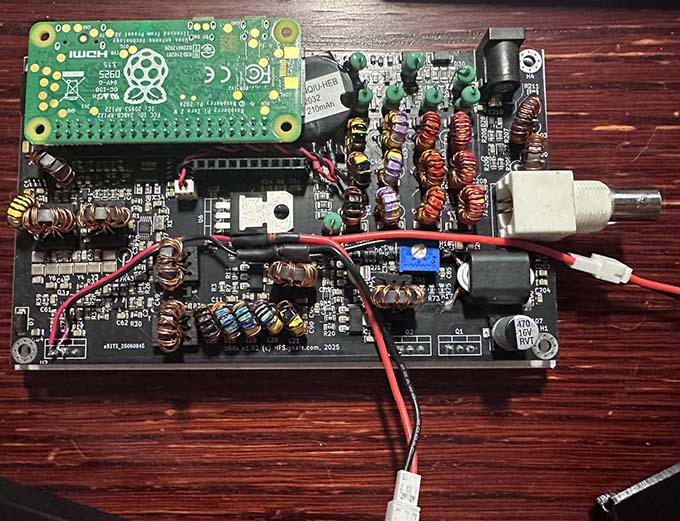
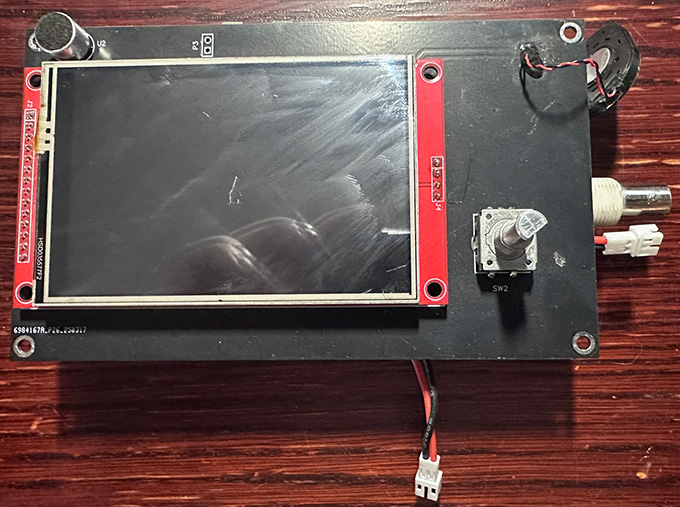
Reconnect the display board to the main board
Now we can start reassembling everything. Start with the upper plate, then the left plate. On the right plate, hook up the fan connector and carefully work the excess wire into the zBitx between the two circuit boards. Insert the right plate fully and snug down the nut on the BNC connector. Attach the battery connector to the lead coming out of the bottom of the zBitx. Stow the excess wire inside the bottom extension by working it into the hole. Situate the bottom plate in it’s place and add the face plate, securing everything with the original screws and nuts.
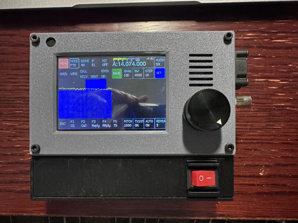
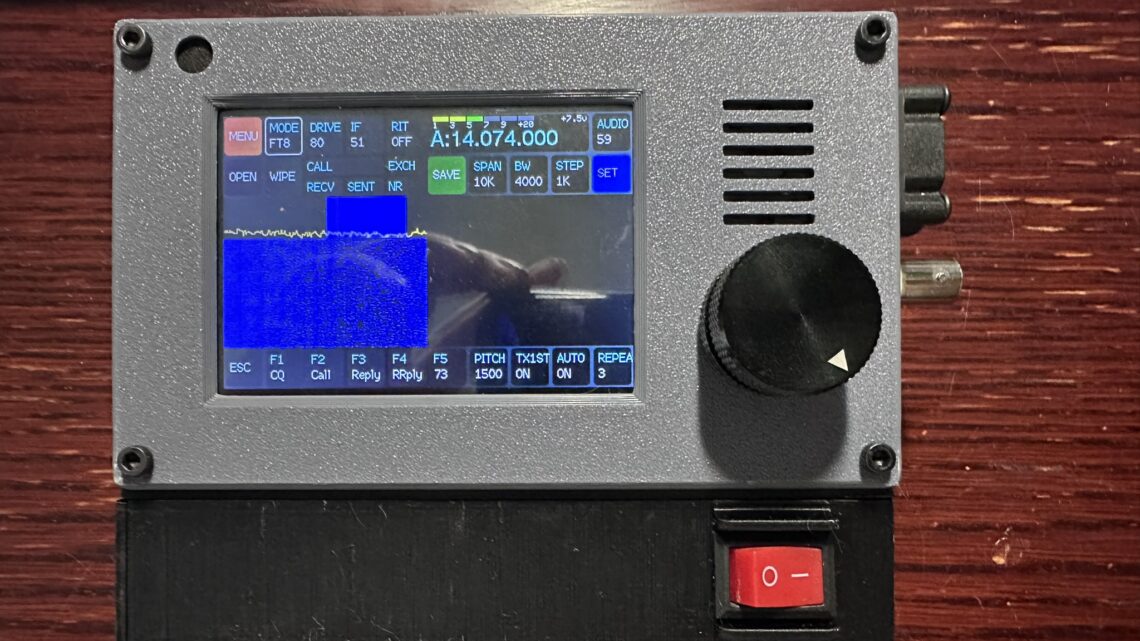
At this point you should have the fully assembled zBitx with it’s new case. I hope you’ve enjoyed this tutorial, or at least find it helpful. If you have an questions be sure to leave me a comment below! Thanks.